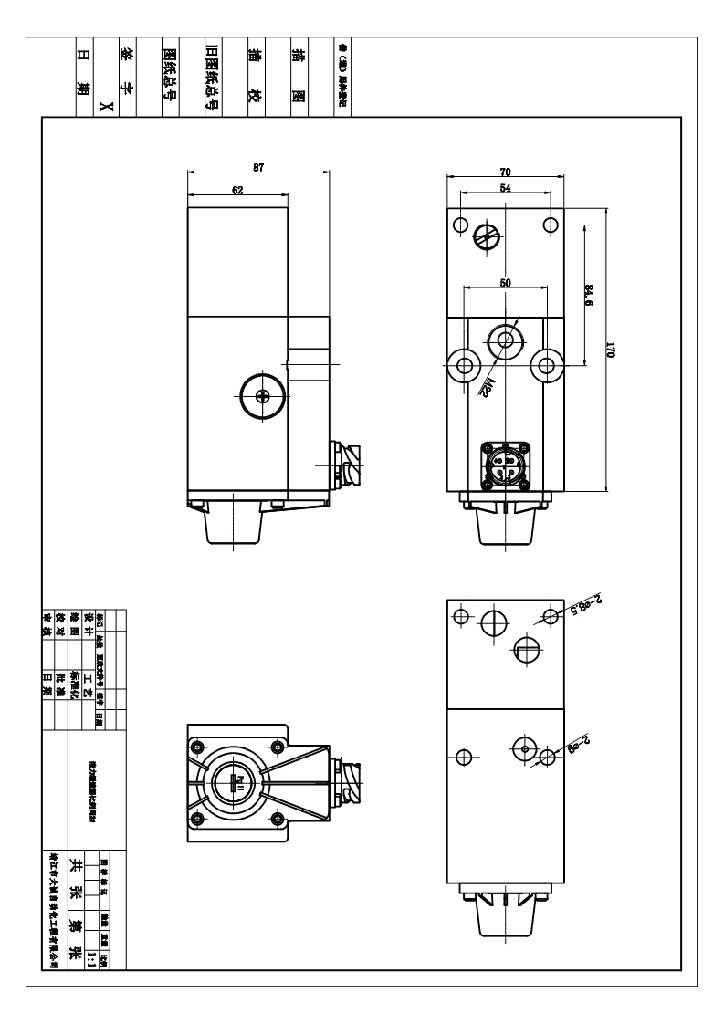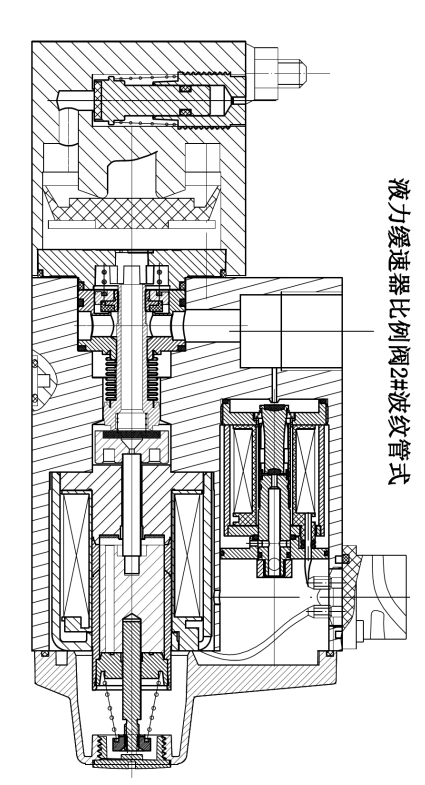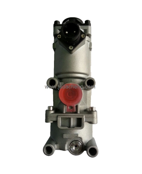
The hydraulic retarder control system comprises pressure reducing valves which can switch the pressure of the air to be supplied from a pressure air source to an air/liquid conversion device at least to a low pressure, an intermediate pressure and a high pressure, or a proportional electromagnetic valve which can reduce and adjust the pressure of the air in a stageless manner, and running speed detect devices, which detect the fact that the running speed of a vehicle is equal to or slower than a given running speed. When there is given a detect signal by the running speed detect devices, then the pressure reducing valves, or the proportional electromagnetic valve are or is switched over to a pressure higher than a set pressure for running speeds exceeding the given running speed, so that the high pressure air from the pressure air source can be supplied to the air/liquid conversion device
In the field of large-sized vehicles such as trucks, buses and the like, as disclosed in U.S. Pat, there is known a vehicle which includes a hydraulic retarder system. The hydraulic retarder system, when the vehicle runs down along the downward path, generates a braking torque to thereby reduce the high speed of the vehicle and prevent a friction brake device from fading due to the rise in temperature, so as to improve the safety of the vehicle and the durability of friction members. The hydraulic retarder system includes a rotor fixable to a rotary shaft such as a propeller shaft or the like which is rotated together with a wheel, and a stator fixed to the body of the vehicle in such a manner that it is not rotatable. In the hydraulic retarder system, the rotor is connected and fixed to the rotary shaft by a clutch device, operation liquid is stirred by the rotor, and there is generated a brake torque due to the friction loss of the operation liquid and also due to the loss of collision with the stator.
However, since the brake torque to be produced by the hydraulic retarder system, when the pressure of the operation liquid within the hydraulic retarder is constant, is obtained according to the number of revolutions of the rotary shaft, that is, the running speed of the vehicle and thus the brake torque obtainable in the low speed running state of the vehicle is small, there is a possibility that a driver unfamiliar with the hydraulic retarder system can drive his or her car to ram a car ahead when the driver is going to stop the vehicle or when driving at the low running speed. Also, when the driver continues to run the vehicle at the low speeds of 30 to 50 Km/h in a long downward slope such as a hill road, the speed reduction obtained by the hydraulic retarder is small, resulting in an inferior operation feeling.
1. Big brake torque.
2.Light in weight, and small size.
3.Strong continous brake power.
4.Low energy costing
5.Low temperature in working space
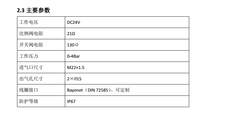
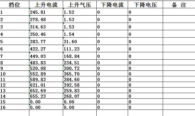
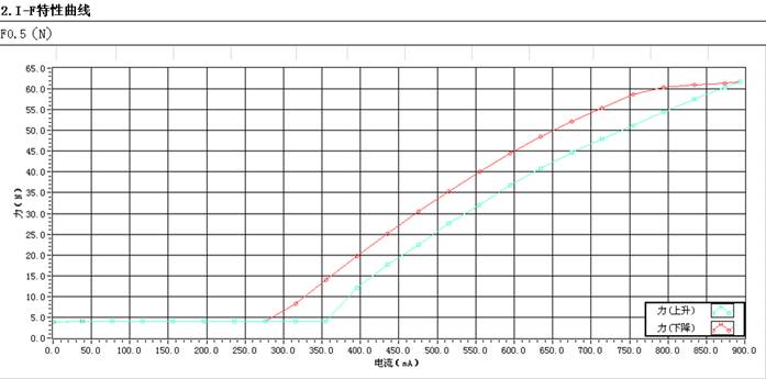
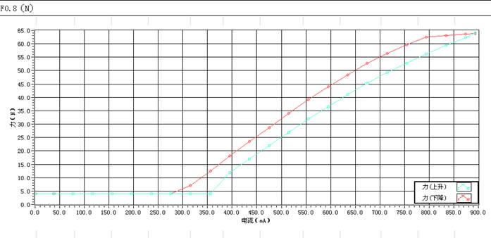
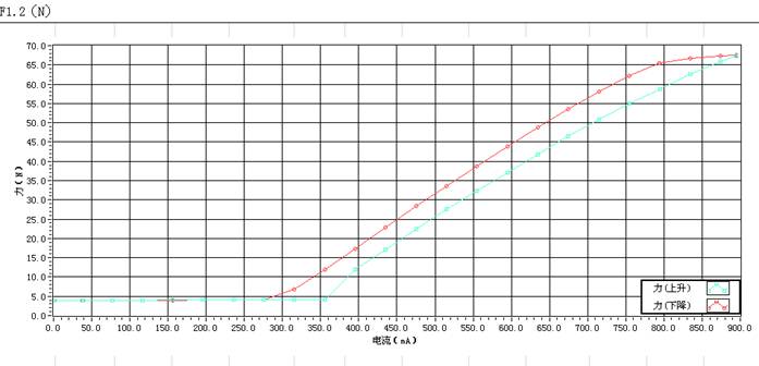
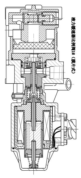
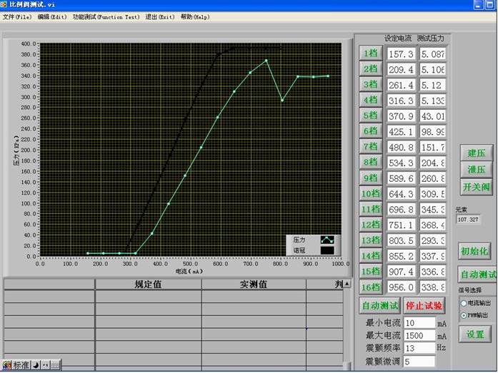
There are 5 gears according to required braking force, when the hydraulic retarder begins working. The inlet oil is different to each gears, while how much oil must be in-put, then it will all depend on the proportional valve.
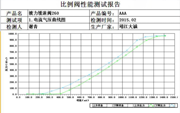
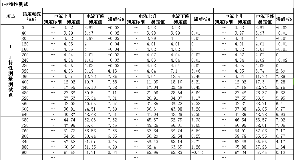
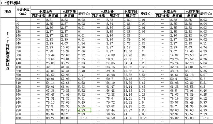
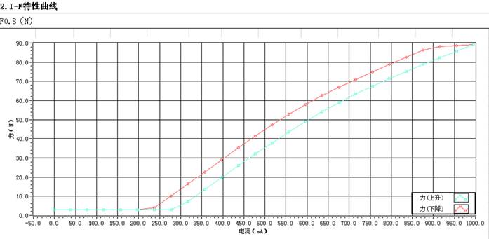
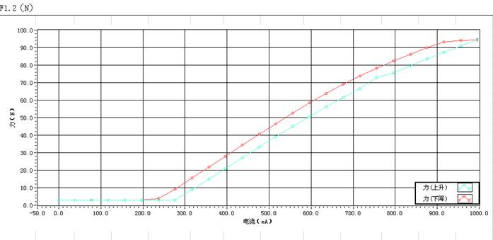
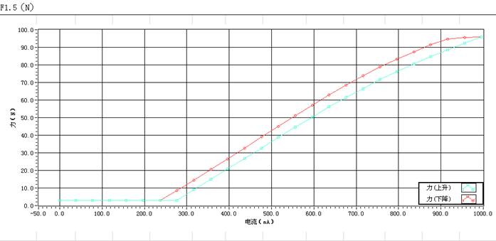
When the driver chooses a gear, the hydraulic retarder will give a electic signal to the proportional valve, and the proportional valve will adjust the air displayment to the change of current, thus get different brake force.
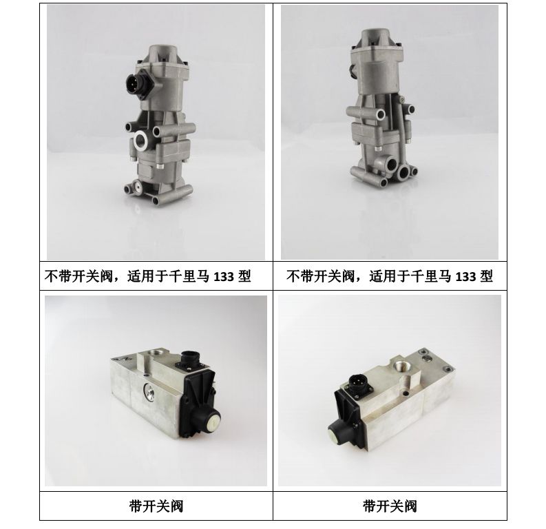
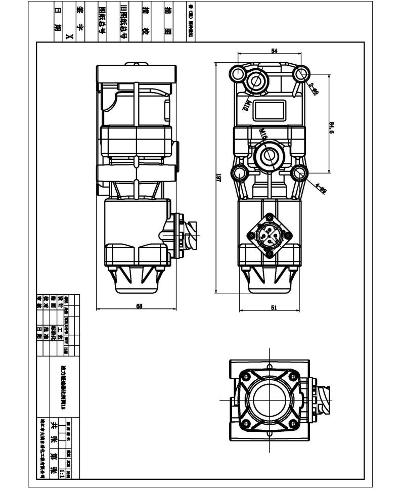
Now we have two hydraulic retarder proportional valve,with switch for NORGEN and without switch for VOITH.
3、相关图纸
4、液力缓速器检测报告
5、相关图纸
